This post is about VPCS and RIP version 2 configuration in a very small environment. Not the topology rather the small cost yet robust testing possiblity is the important thing here.
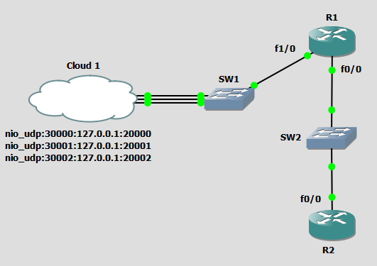
Here is an overview of my topology.
The routers have these basic configurations.
R1:
- router rip
- version 2
- network 10.0.0.0
- network 192.168.0.0
- interface FastEthernet0/0
- ip address 192.168.0.150 255.255.255.0
- interface FastEthernet1/0
- ip address 10.1.1.1 255.255.255.0
R2:
- router rip
- version 2
- network 2.0.0.0
- network 192.168.0.0
- interface Loopback1
- ip address 2.2.2.2 255.255.255.255
- interface FastEthernet0/0
- ip address 192.168.0.151 255.255.255.0
This is all we need because this way we have a loopback at the very end of our network which we can try to reach from the virtual machines. Let’s get back to the VPCS, these are small “programs” accompanying the GNS3 and are only exsisting for the very purpose to simulate the behaviour of a PC from network perspective. We can either add them as a VPCS from GNS3 with GUI or we can use their executable from the original installation directory. Mine looks like the one below.
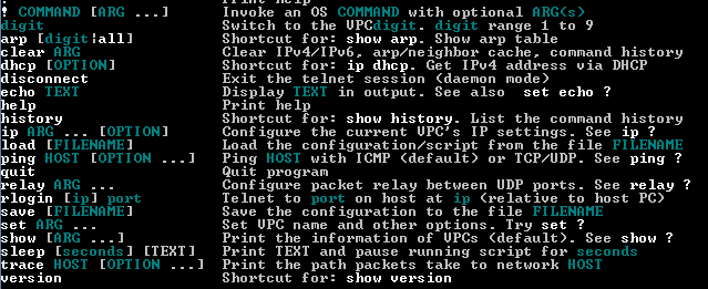
If we start the executable we get a prompt like this.
At the end of the prompt we see this.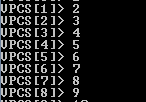 As you can see with the numbers from 1 to 9 we can switch between the virtual pc-s, and use them as we like, configure them with IP addresses, and telnet from them or whatever we want. Here is a list of what we can do with these machines.
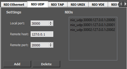
But how does this go and connect to the Cloud in the GNS3? If we go and take a closer look at the Cloud we can see we have an NIO_UDP ear of the configuration tab.
I have added 2 ports now here is a screenshot from my configured VPCS which was brought to you by the “show” command. 🙂
We can see that the Cloud’s Remote port corresponds to the VPCS Local port, and the Cloud’s Local Port corresponds to the VPCS Remote port(RHOST:PORT). Currently I have the R1 set as default gateway on these VPCS and according to the routing table of the router:
I must be able to ping any device from any device in my environment!
VPCS(2) -> R2(Loopback1)
Now let’s try to ping the VPCS(3) from the Loopback1 interface of the R2 router!
The first packet is lost due to ARP but after that it goes very smooth.
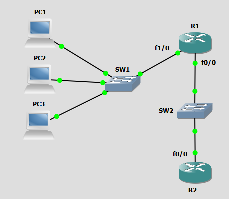
This is the same topology, only the difference is that each VPCS now has it’s own console where we can not switch to the other. I belive the previous version I have showed is more efficient in many ways. But you know what they say, dealer’s choice. 🙂
I know the latency is pretty high but considering that I am running an emulated router using a virtualized network which is ran by the GNS3’s hypervisor in a Virtual Machine running on the back of the VMware Workstation’s hypervisor I think it’s not just amazing but pretty awesome. 🙂
Cheers,
Daniel
